Wind tunnel testing
What is it?
Wind tunnel testing is a design assisted testing procedure for obtaining wind pressures. It can be carried out on scaled models of a building and surrounding terrain to study the effect of natural wind on the facades. This enables the wind loads on the facades to be determined.
Why is it needed?
The engineering and design of a building facade is informed by the wind loads. It is therefore in the interest of design efficiency and elegance to determine the most accurate wind loads to avoid over-engineering of the facade systems and glazing. A desk study/calculation using the guidance of Eurocode BS EN 1991-1 can be sufficient for standard building forms. However, when the building geometry becomes more complex with irregularities making it non conforming to the basic building geometries outlined in the Eurocode the calculation becomes very conservative and more of an approximation.
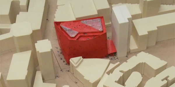
62 Buckingham Gate wind tunnel test model showing surrounds model and the wind tunnel opening
A wind tunnel test provides a more accurate understanding of the maximum wind pressures and in more cases than not it significantly reduces the maximum pressures.
Often the specialist company carrying out the testing will be able to advise on whether there is likely to be an improvement from the Eurocode calculations.
When is it done?
We would expect any wind tunnel testing to be carried out prior to any significant facade structural analysis and member sizing. Therefore it is best completed during Stage 3 Developed Design after identification of each facade type zone.
When the wind pressures are received from testing we carry out an interpretative report to organise the data into pressures for each of the facade type zones. The maximum wind pressures and suctions for each facade type are then taken forward in to technical design to inform the facade design and sizing.
How is it done?
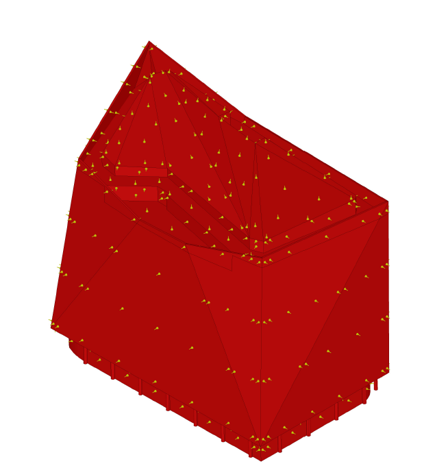
The building geometry is sent to the wind tunnel testing consultants for them to model it to scale. We would then review and advise on the locations of the pressure sensors on the model to ensure that an accurate understanding for all facade types can be generated.
The surrounding buildings are replicated in the model to a radius of 360m. Closely spaced buildings have a big impact on the resultant wind load and act to reduce the wind loads at the lower levels. Should any alterations to the local terrain be known these are represented in the model or in a second re-run of the test.

3D cgi showing the tap locations for review
The simulated wind is directed towards the model through a tunnel. The floor of the tunnel has a roughness equivalent to the town terrain, distance upwind to the shoreline and roughness length to generate the correct turbulence.
The walls extend the effect of the roughness elements whilst the turbulence grid disperses the wind so that it has uniform turbulence and is not affected by the tunnel wall in a way that is unnatural.
By varying the floor roughness and specially designed turbulence generators the effects of various types of terrain roughness upwind and associated turbulence eddies can be reproduced at the model scale.
All of the factors affecting the wind pressure are therefore artificially accounted for and the wind speed is modified to take in to account of the building location, direction (the model can be rotated and subjected to different corresponding wind speeds), time of year, risk, altitude, topography, terrain, height above ground and surrounding buildings.
The small changes of pressure on the building surface are detected electrically when the pressure generates a proportional voltage signal at each sensor.
Interface would typically carry out the initial desk study of the wind pressures to provide estimations of the wind pressure magnitudes. If we believe a wind tunnel test will provide value to the project and the Client then we would encourage it to be carried out and at the earliest opportunity. The wind tunnel test would supersede the desk study pressures and the new pressures would inform the technical design and allow for a more informed tender.
Case study
62 Buckingham Gate, designed by Pelli Clarke Pelli architects, is a prism-like structure which did not closely fit the stereotype building shapes within the Eurocode. Most crucially the facetted sloping facades did not resemble the cuboid shape with the Eurocode standard. The over-sailing cantilevered glazing above roof level had to be simplified and assumed to be a uniform height despite varying between 1.5m and 9m and any effects of the plant rooms offset behind could not be considered. The wind pressures and suctions on the open canopy nestled between 62 Buckingham Gate and its neighbouring building could not be accurately represented.
The degree of approximation required would have contributed to either an oversized or undersized facade system. For 62 Buckingham Gate the wind tunnel testing results produced lower wind loads on the facades than had been calculated using the Eurocode standard, therefore enabling a more efficient design.


